Building confidence
The focal point of our efforts is building the main hull structure of Quicksilver. This huge task is made possible by engineering companies that have supported the project in such ways as purpose-making components to our design, or donating off-the-shelf components, or donating standard or specially-made materials that match our requirements, or contributing specialised facilities and expertise.
Contributing companies have all sorts of specialisations. The range of facilities, expertise and experience needed to progress construction from start to completion is vast, so these collaborations are vital. Firms large and small are helping us create a boat that is every bit as pioneering as it is inspiring.
Extensive design work and analysis must take place before any components are manufactured for the boat. This work has been undertaken by highly-experienced specialists, and has often involved the use of advanced analytical software tools, such as Ansys, NASTRAN and LS-Dyna.
Here are some insights into the types of work undertaken so far ...
Process engineering
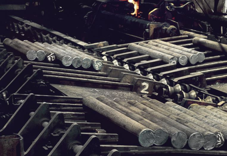
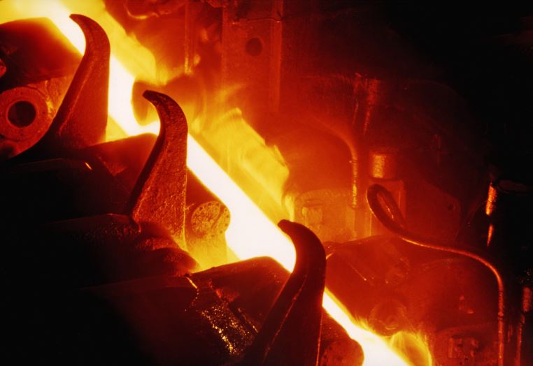
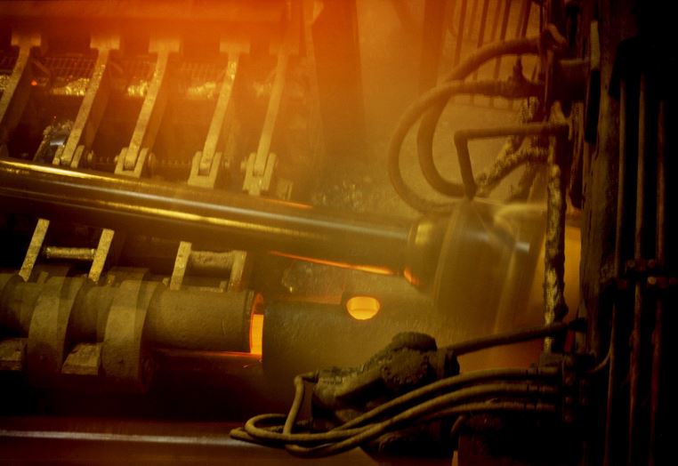
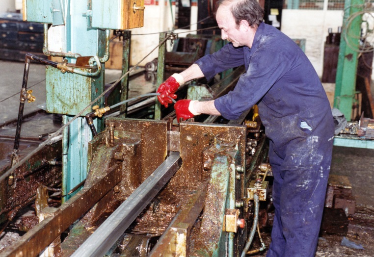
An early breakthrough for the project came when a major British company showed its willingness to manufacture for us free of charge. Famed tubemakers Accles & Pollock made a substantial quantity of cold-drawn seamless high-tensile steel tubing for the boat's main hull structure. It was significant because we knew our plan to build a boat could only reach fruition if companies joined in like this.
The bulk of the work was undertaken at their plant at Oldbury near Birmingham, but the initial stages of the production process took place at the British Steel foundry in Wednesfield near Wolverhampton.
Initially, the steel was in the form of solid cylindrical billets. These were bored-through to a basic tubular form known as a 'tube hollow' and drawn out to longer lengths, then when the process transferred to Oldbury the tubing was shaped into square-section and heat treated. It was now in the extremely rare, supremely strong, BSI T59 specification, at 16-gauge, that we required. This has a tensile breaking strain of 55 tons per square inch, yet the tube wall-thickness, at a mere 1.59mm, saves weight.
By their support, Accles & Pollock had set Quicksilver's construction in motion. We are particularly thankful to Paul Rollason, who led their technical input to our project.
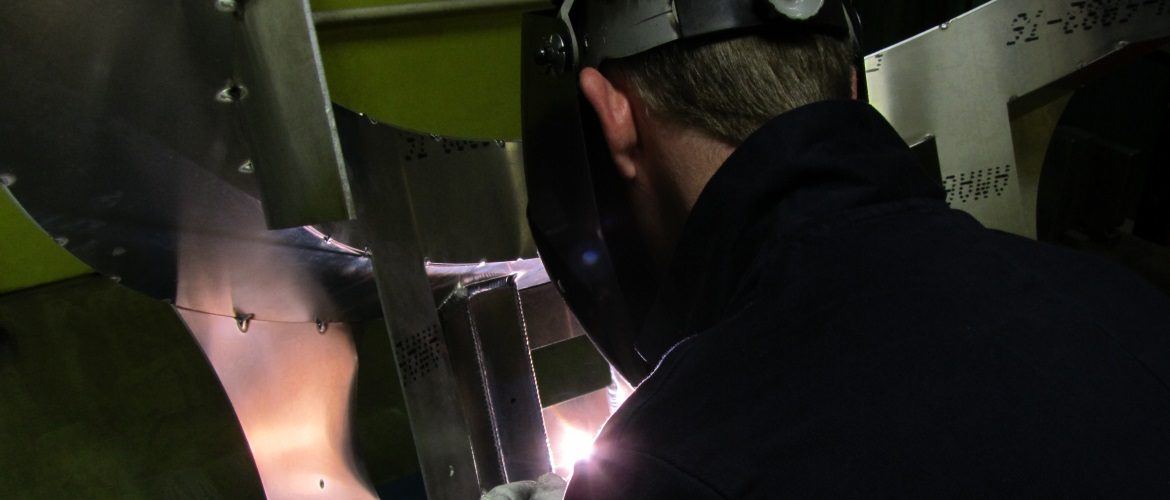
Fabricating steel structures
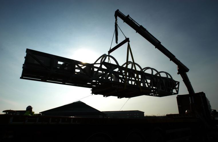
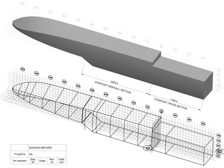
The next stage of building the boat was to employ the steel tubing to fabricate a large spaceframe – the primary element of the main hull structure. The spaceframe was designed by Glynne Bowsher. It is analogous to the skeleton in a human body, in that everything else is attached into and onto it.
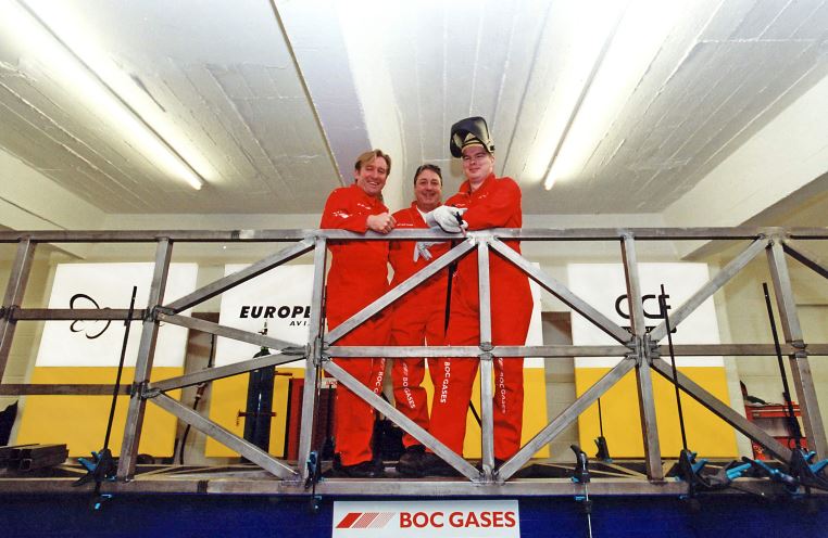
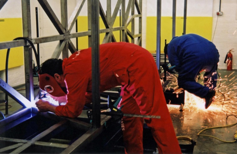
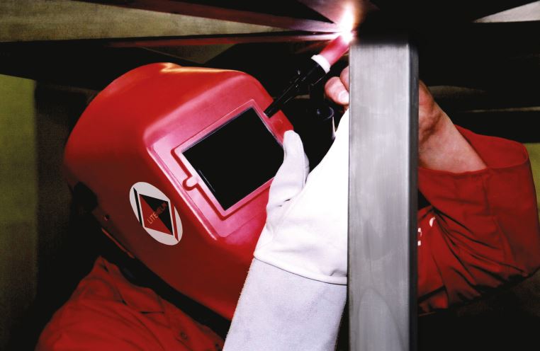
BOC Gases played the leading role. Due to the rare type of steel being used, they had first to develop a special welding procedure, which was duly tested and certified by The Welding Institute in Cambridge. Three of BOC's developmental welding specialists were assigned to the spaceframe fabrication: Craig Rollinson, Steve Moynihan and Chris Birch. This task occupied several hundred working hours. Over 130 individual tubular pieces had to be precisely cut, then carefully positioned on a purpose-built jig and TIG-welded into place.
When a decision was taken subsequently to modify the spaceframe to create a different version of the boat, Roland Snell designed the necessary revisions. He also designed engine-mountings, again in steel. Radshape Engineering of Aston, Birmingham, implemented the modifications and manufactured the new parts.
Fabricating aluminium structures
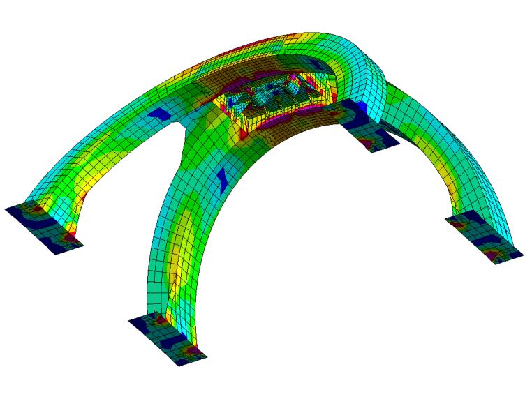
A row of four aluminium arches add strength and rigidity to the spaceframe. Longstanding sponsor Radshape Engineering has made three of these, to our designs. To begin waterborne trials, we only need these three.
Achieving lightweight construction was a key goal. We conducted finite-element analysis (FEA) when designing each arch, to determine where material thicknesses could be reduced to save weight without unduly diminishing strength and stiffness. Analysis modelled the forces that will be transmitted through the arches when the boat strikes disturbances on the water's surface at high speed.
The design of each arch is distinctly different, as they all have important secondary functions. For example, the third arch doubles as the upper-rear mounting point for the engine. Any or all of them can be unbolted from the spaceframe to facilitate the removal of the engine and/or access to other components housed within the hull.
Radshape laser-cut all the constituent parts. Material thicknesses vary from 3mm to 6mm. Arches one and two are made from BSI 6082-T6 aluminium sheet, while arch three is made from BSI 7020-T6 aluminium sheet with a steel engine-mounting assembly bolted into it.
AHT Ltd. of Dudley in the West Midlands will heat-treat the arches later, augmenting their strength.
Patternmaking
With much of the main hull structure now built, we turned our attention to the other tasks needed for it to go on the water. The components described above can be thought of as the major internal structural elements, so now the boat's external structures are being built.
A decision having been made to use composite materials for the outer hull, it was necessary to manufacture a variety of patterns and moulds first. These serve as foundations from which a hull of the desired shape can be formed. In the case of the patterns, some are constructed from timber, while others are machined from solid blocks of a high-density patternmaking foam material.
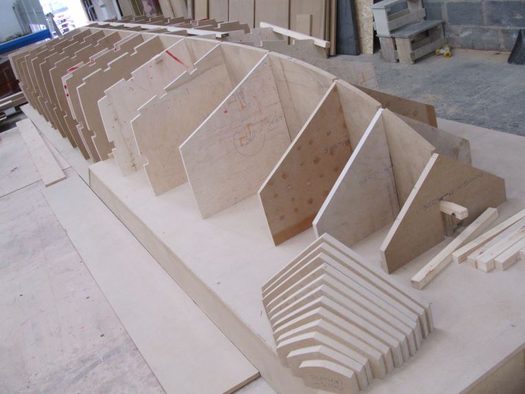
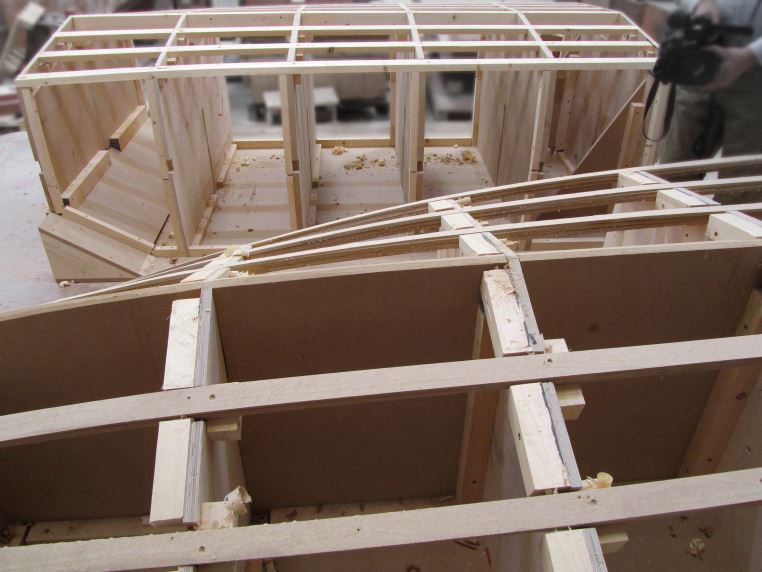
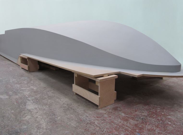
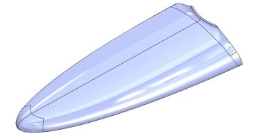
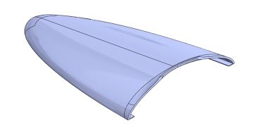
The largest one is pictured here. Made entirely by hand, it is the pattern for the lower portion of the hull, extending aft from the foremost tip of the bow. As can be seen, timber was used throughout.
This impressive example of the patternmaker's talents is nearly 25 feet long and weighs approximately one ton. The craftsmanship involved was of the highest order, employing skills honed by lifetimes of experience in what is an intuitive yet exacting art.
Our grateful thanks to Shaun Wright and his colleagues at Millfield Patterns in Newcastle upon Tyne for their kind support of our patternmaking programme.
Manufacturing carbonfibre/Airex structures
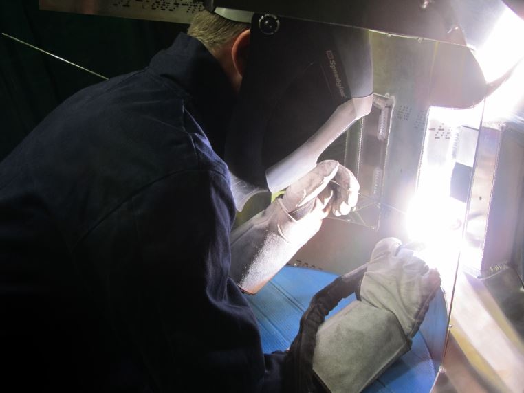
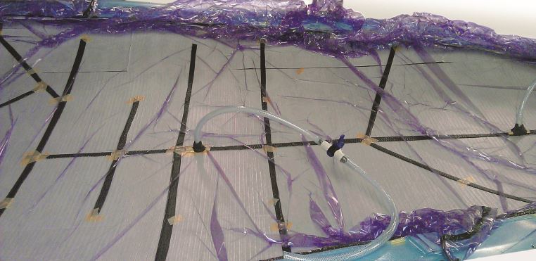
Shown during manufacture is the 2.35-metre-long foredeck element of the boat's outer hull structure. Multiple layers of carbonfibre have been laid-up in a purpose-made fibreglass mould. A vacuum bag has been tailored snugly over it so that air can be extracted and the carbonfibre infused with a carefully-formulated mixture of epoxy resin and hardener drawn in via a system of plastic tubes and taps by an electric vacuum-pump.
While the carbonfibre layers are compressed firmly together under vacuum, a process of curing takes place, hardening the fabric to a solid form. The white layer seen here is an absorbent material which soaks-up excess resin and is disposed of with the vacuum bag, post cure.
When this stage of the process was completed, a 15mm-thick layer of Airex structural foam was laid-up on the carbonfibre and bonded firmly to it by repeating the vacuum-bagging process. Airex is a lightweight core material made by the Swiss firm 3A Composites SA.
Further layers of carbonfibre were then applied atop the Airex, creating a sandwich-construction panel that's very stiff and strong for its weight. The inner and outer carbonfibre skins are both 1mm thick, resulting in a panel thickness of 17mm.
The foredeck was manufactured to our design by Nottingham firm Competitive Carbon Composites. They made the fibreglass mould from a high-density foam pattern machined for us by Trident Foams Ltd. of Furness Vale in the High Peak district of Derbyshire.
Manufacturing Kevlar/Baltek structures
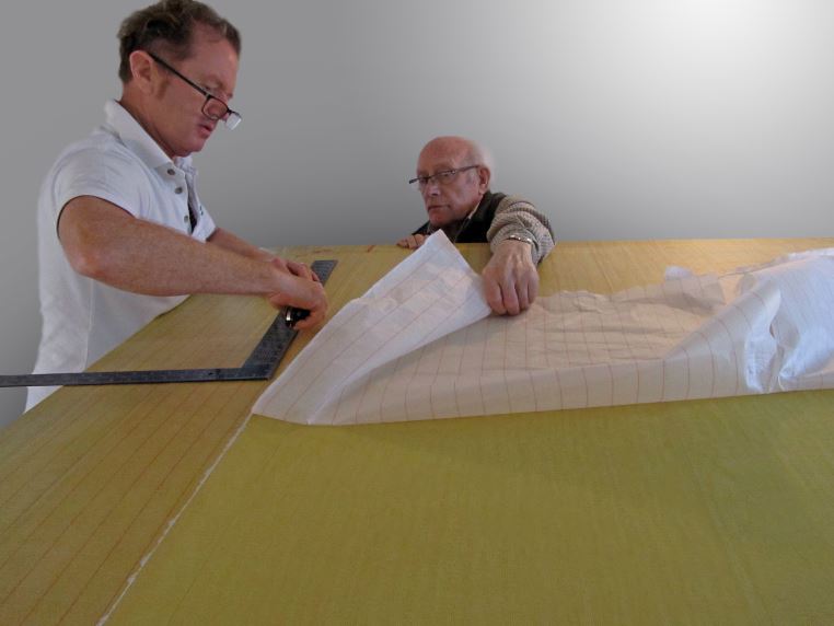
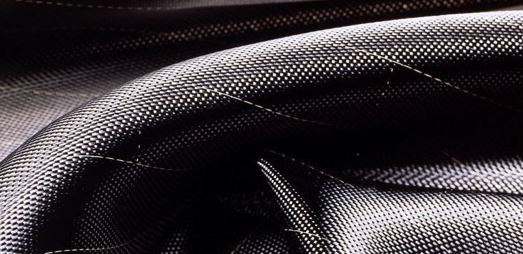
While carbonfibre and Airex structural foam are being employed in some regions of the outer hull, the predominant outer-hull materials are Kevlar and Baltek, the latter being a highly-engineered balsawood material manufactured by 3A Composites SA. When using Kevlar and Baltek, the techniques we employ are very similar to those described above for the foredeck's construction, including introducing epoxy resin and hardener by the vacuum infusion method, but the skins are made of Kevlar and Baltek is the core material.
In the photo, the lengthy process of laying-up Kevlar and Baltek is seen in progess. Pictured are composites guru David Johnson of Wessex Resins & Adhesives Ltd. and aerospace veteran Bill Woodhouse, who was a key part of the team that built the ThrustSSC supersonic car. They are carefully removing part of a protective layer of peel-ply prior to commencing the next stage of a process that is gradually building-up the outer hull structure.
3A Composites and Wessex Resins & Adhesives, in supporting our project, have not only donated substantial quantities of materials, but are also inputting their specialised expertise on an ongoing basis. Furthermore, M. Wright & Sons Ltd. generously manufactured for us all of the Kevlar woven material we need to complete the outer hull.
Images © QWSR Ltd.