Stage by stage, the story of the construction of the outer-hull structure. A tantalising preview of the boat's elegant outer shape


Our primary focus for some considerable time now has been the boat's outer hull structure. The goal was to turn our concept for this into the real thing. Work initially was taking place behind closed doors, with little or no photos released, as there are aspects of the way the boat is built that are as yet confidential. The BBC is continuing to follow our progress with frequent filming sessions of not only this work, but also a wide variety of our other activities, but the fruits of that will not be seen until the boat is almost ready to go on the water. So to lift the lid a little, we've been gradually releasing photos recently that provide a tantalising glimpse of the external size, shape and construction of the outer-hull structure, to demonstrate the nature and scale of the work that's been going on.
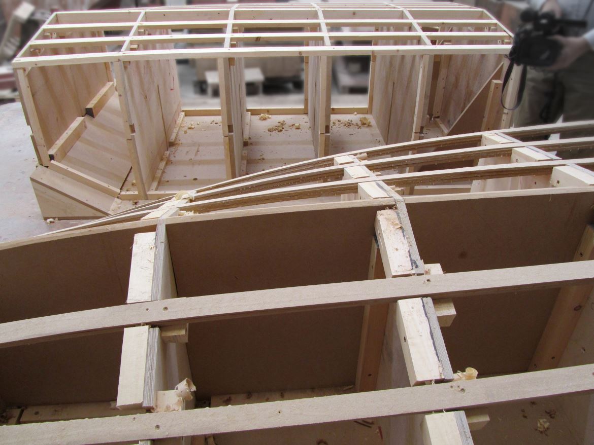
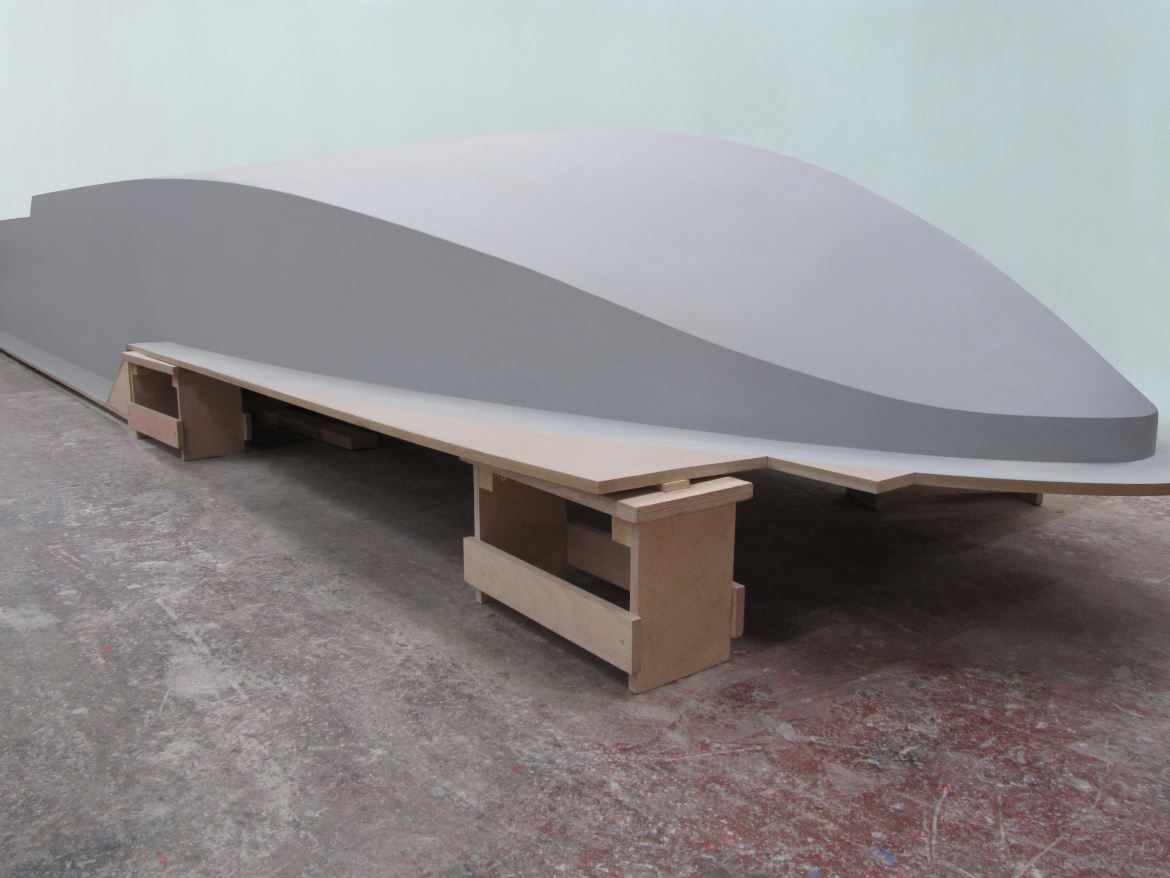
When composite materials are being used in construction, as is the case with Quicksilver's outer hull structure, a set of patterns and moulds must be made first, to provide the foundations upon which those materials can be ‘laid-up’ in the desired form. What is seen at the top of this page is the very largest pattern, representing the lower half of the outer hull from the tip of the bow to a point some 25 feet aft. The shape of the bottom and flanks of the boat can be clearly made out, as can the step – a feature on the underside of the hull that will help the boat to 'unstick' from the water and rise up onto the surface, into the planing condition, as it accelerates from low speed to higher speeds.
The area of the hull that this huge pattern represents is delineated by the red line in the CAD image at the foot of this page, which also shows the relative positions of other key elements of the boat – principally the main-hull spaceframe, Rolls-Royce Spey turbofan engine, air-intake module, main sponson-arm, and foredeck. It is an outstanding example of the patternmakers' craft, made entirely by hand with time-honed, traditional methods by our good friends at Millfield Patterns Ltd. in Newcastle upon Tyne. With timber being used throughout, its weight has been estimated at one ton.
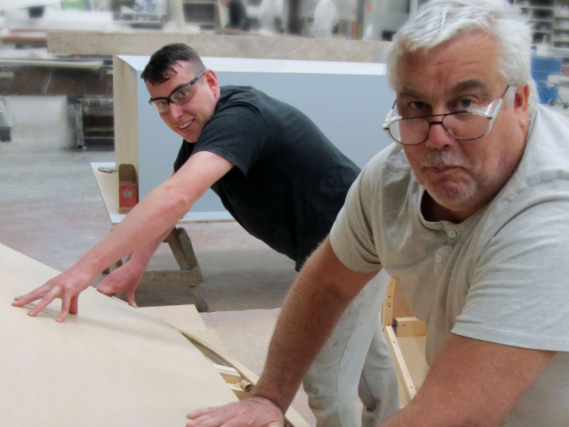
Pictured hard at work at the top of this page is Millfield's very hands-on Managing Director, Shaun Wright, who with Eddie and Steve – also pictured – who made a truly monumental contribution to the progress of the Quicksilver project.
One further, far smaller, pattern will be needed for the underside of the very front of the boat, and that is the pattern for the chine – a sharp-edged, curved lip around the bow which, like the step, will help the boat to rise up onto the plane. This pattern will follow later, as the chine is to be made as a separate component that will be added to the hull nearer the time of its final completion.
Engineering properly, not cutting corners
The construction of the huge pattern shown at the top of this page was but one of a lengthy series of preparatory activities that took us to the stage where, at long last, we could make the outer hull of the boat. We've always worked along proper engineering lines, as cutting corners – while it saves bags of time initially – is the surest route to failure further down the line. Our preparatory work has involved many people and can be said to have started with conceptual design at the very outset, which determined the ideal outer-hull shape. It was to renowned marine architect Lorne Campbell that responsibility fell to devise the shape of those regions of the boat that come into direct contact with the water – although he did this in close collaboration with several others, most notably our long-serving aerodynamicist, Mike Green, who was formerly the Chief Aerodynamicist at British Aerospace at Woodford in Cheshire.
Once the shape had been finalised, scale-model testing was conducted in verification in the windtunnel at Salford University, under the eyes of Mike Green. But this was only after a great many test-runs had been made with a turbojet-propelled, radio-controlled scale model on a private lake near Telford, followed by hydrodynamic computational fluid dynamics (CFD) analysis conducted by marine engineer Mike Coulthard, who has long and extensive experience in this highly-specialised type of work.
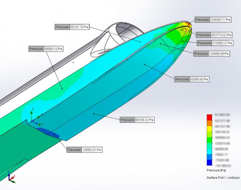
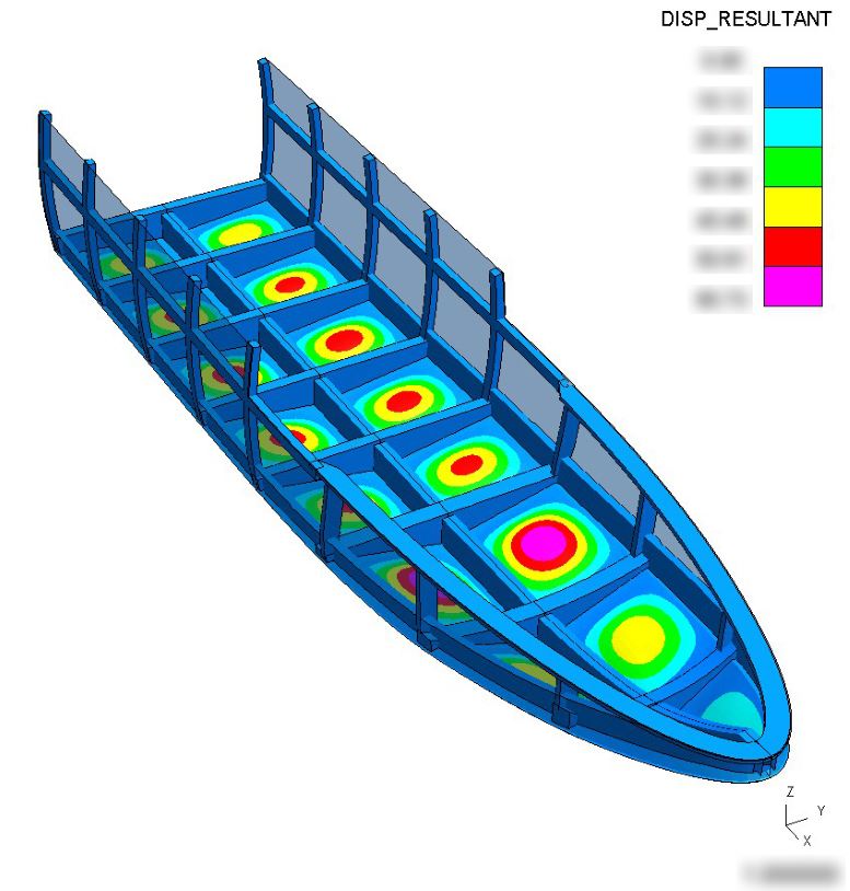
The CFD image shown on this page was part of a simulation to assess the water pressures that will be exerted on the external surfaces of the main hull as the craft accelerates at the beginning of a run. Although the figures (in Pascals = Pa) are obscured here for reasons of confidentiality, the colour-coding of the image clearly indicates the concentrated areas of higher pressures (shown in red and yellow) at the extreme forward tip of the bow, and the very much larger regions of lower pressure (green and pale blue) further back, and even a small region of negative pressure (dark blue) immediately in front of the step.
We undertook CFD analysis of this kind because we needed to gain a thorough understanding of the loadings water imposes on the hull before we could go on to finalise the hull's structural design.
Detailed design work, as it steadily progressed, included extensive finite-element structural analysis (FEA) by Simon Hart, some very specialised complex-surfacing work in CAD by Tim Harrison, and the various stages of selecting and sourcing appropriate composite materials; the latter work closely involving Mark Evans. A key aspect of this stage in the whole procedure was the manufacture of dozens of small samples of the outer-hull structure for assessment in a series of 'three-point' bending tests to destruction, to verify their strength. This for us was standard procedure, as we have always tested our ideas thoroughly before committing to them. Then, finally, there was impact-testing conducted at Loughborough University, to assess the outer hull's resistance to striking objects which might be floating in the boat's path when it is at speed.
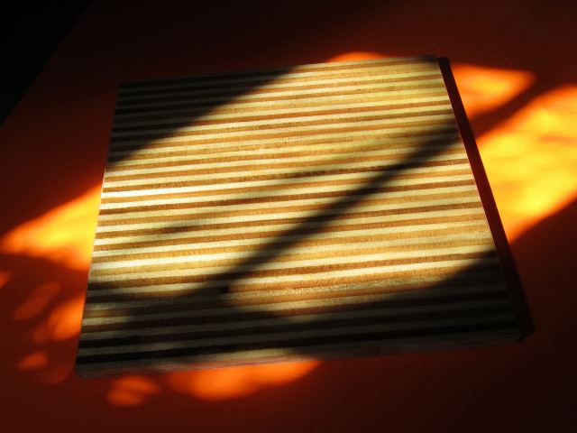
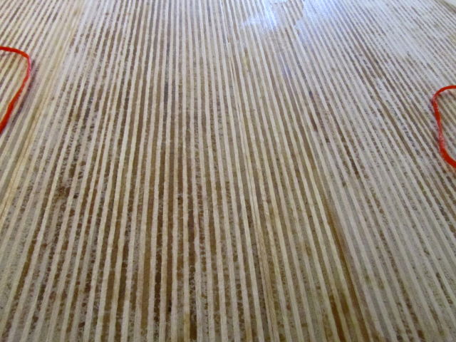
Among the images displayed on this page is one showing just a few of the many small samples of the outer-hull's Kevlar/Baltek sandwich structure that were 'three-point-tested' before we committed ourselves to manufacturing the full-sized component. Data from the tests were painstakingly scrutinised as part of our efforts to perfect the production process, and there were several iterations and multiple sets of tests before we settled on what we believe to be the best method. One key aspect we were exploring was the fibre-to-resin ratio. Additional resin enhances strength but also adds more weight, which is undesirable, so we experimented to arrive at the optimum compromise. It was notable that, in every single test, both Kevlar skins remained intact after the internal structure had broken, indicating that Quicksilver's outer hull would remain watertight in all but the most severe circumstances.
During the period much of this work was going on, the first element of the outer hull structure – the foredeck – was made. This task started with the machining of a high-density foam pattern, from which was cast a fibreglass mould, into which multi-layered skins of carbonfibre were laid-up on either side of a 15mm-thick core of Airex structural foam. This produced a foredeck of very strong yet lightweight sandwich-panel construction that will be joined to the lower element of the outer hull in due course.
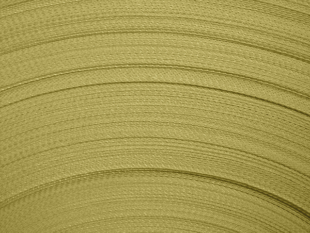
So, right now ...
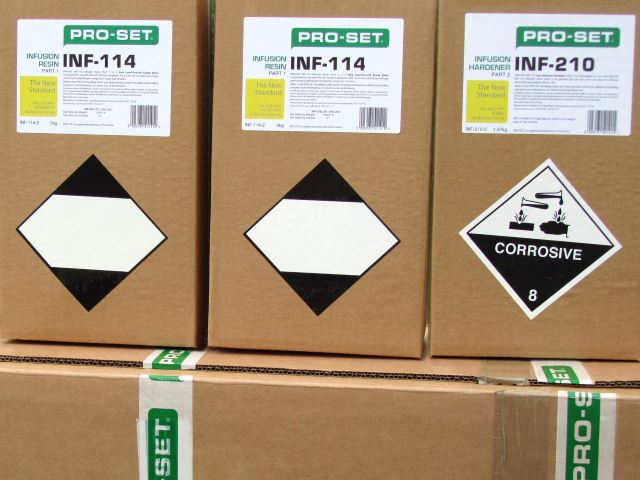
Construction of the lower portion of the outer hull is well under way and progressing steadily as our time allows. Being of sandwich construction, it too will be immensely strong in relation to its weight. Skins made up of multiple layers of Kevlar go either side of a 12mm-thick core of Baltek, a highly-engineered balsawood material produced by 3A Composites SA of Sins, near Zurich in Switzerland. 3A kindly donated the large volume of Baltek we needed some time ago. Then, last summer, we collected a huge consignment of Kevlar woven specially for us by M. Wright & Sons Ltd. of Quorn in Leicestershire. Lay-up work is proceeding at Quicksilver's secret 'Skunk Works' deep in rural Lincolnshire. The process involves extensive use of the infusion method, whereby a mixture of epoxy resin and hardener is drawn into the Kevlar fabric under vacuum. The vacuum state compresses the layers of Kevlar firmly together, and is maintained throughout an eight-hour curing cycle that results in the fabric hardening to a solid form. A similar technique is being used to adhere the Baltek core firmly to the Kevlar skins.
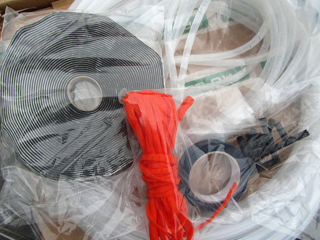
All three 'ingredients' that make up the outer-hull structure are shown in a 'revolving' image-frame on this page. We are most grateful to 3A Composites, M. Wright & Sons, and also to Wessex Resins and Adhesives Ltd. of Romsey in Hampshire, who have generously donated substantial quantities of West System Pro-Set epoxy resin and hardener, together with myriad consumables ranging from such specialised items as vacuum-bag film, remesh, peel-ply and flash-tape, to workaday items such as plastic tubing, mixing-pots and wooden stirrers. They also made the dozens of small structural samples to our various specifications and undertook the strength-testing of them in their superb laboratory facilities at Romsey.
Also shown on this page is a 'revolving'sequence of images showing various stages of the vacuum-bagging process, and finally showing a section of the outer hull with the layer of Baltek core material successfully applied in place.
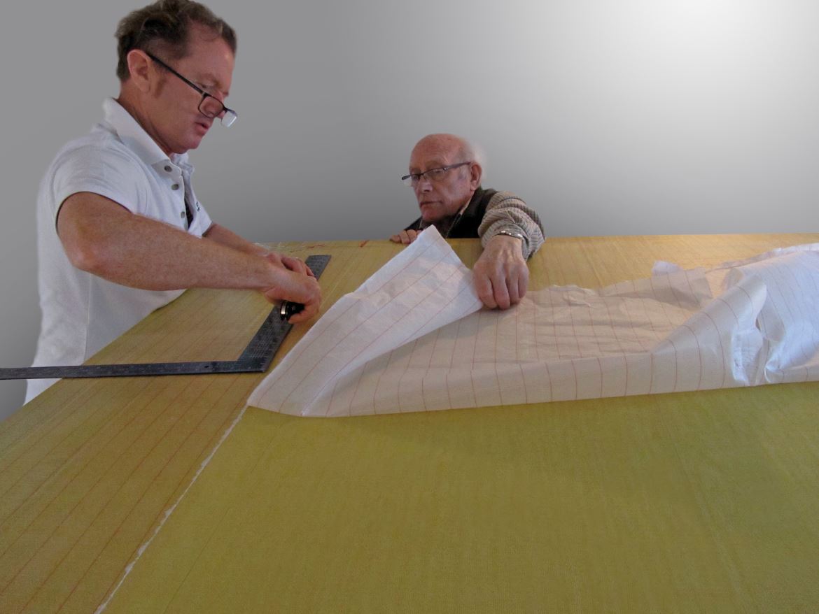
In the photo at the foot of this page, the lengthy process of laying-up the composite materials is seen to be well under way. Pictured there are our composites guru, David Johnson of Wessex Resins & Adhesives, and aerospace veteran Bill Woodhouse, who was a key part of the team that built the ThrustSSC supersonic car. They are seen carefully removing part of a protective layer of peel-ply prior to commencing the next stage of a process that is gradually building-up the outer hull structure.
There's plenty more to do. A variety of metallic fittings will be incorporated into the structure during construction to serve as mounting-points for the outer hull to be attached to the boat's primary structure – the high-tensile steel spaceframe, which has already been built.
The final stages of building the outer hull will involve adding a thin layer of fibreglass to the exterior surfaces and spraying-on a paint system to complete the job.
Overall, the outer hull's design and construction is by far the most complex and time-consuming task ever undertaken in-house by the Quicksilver project, and it has been occupying most of our attention for longer than we would ideally wish. However, the job has to be right first time, so the care and effort being expended is entirely justifiable.
Collaboration, a joint effort
In addition to those named above, other specialists who've contributed to different stages of the outer hull's development include Ed Lupton (carpentry for mock-up of outer-hull pattern), Dr Paul Roebuck (carpentry work on outer hull) and Jeff White (carpentry for mock-up of outer-hull pattern).
The industrial supporters of the outer-hull build, in addition to Millfield Patterns, 3A Composites, M. Wright & Sons and Wessex Resins & Adhesives, already mentioned above, are: Competitive Carbon Composites in Nottingham, who made the fibreglass mould for the foredeck, then manufactured the foredeck itself; and Trident Foams Ltd. of Furness Vale in the High Peak district of Derbyshire, who machined the foam pattern for the foredeck mould.
More recently, we were most grateful for the support provided by Simon Davies, when he very kindly overhauled our trusty BOC Edwards E2M18 vacuum-pump. Simon's work in various fields of engineering is the stuff of dreams, and in this respect we would draw particular attention to his skills in building bespoke motorcycles for customers. Click here to see for yourself.
Our thanks to everyone involved – and to our logistics specialist, Bob Johnson, and the rest of his team at BSJ Holdings in Sleaford, as the task of moving patterns, moulds and finished components from one part of the country to another at progressive stages of the build process is not only exacting but potentially back-breaking at the same time, so it's strictly a job for the professionals.
We'll continue to issue images and information on the outer-hull design/build work as time goes on.

Images © Out of the Ordinary