Applying science
One thing clear from the start was that the project would be research-led. Quicksilver is the product of years of experimentation, research and development. We have gained a wealth of experience and amassed a substantial quantity of data by testing scale models in windtunnels and water towing-tank facilities, experimenting with line-towed and radio-controlled models on lakes, and undertaking extensive computer-based analytical studies.
Once it's afloat, the highly-instrumented craft will itself become a testbed, generating in situ data that will enable us to go progressively faster, as well as creating opportunities for further research that may lead to practical applications elsewhere.
Aerodynamics, hydrodynamics, propulsion, structures. The interactions between them. This is the science of speed.
Here are some insights into our research work to date ...
Hydrodynamic computational analysis

The computer-generated image shown here derives from a fluid-dynamics simulation predicting the water pressures that will be exerted on the submerged external surfaces of the main hull as the craft accelerates at the beginning of a run. Although the figures (in Pascals = Pa) are obscured here for reasons of confidentiality, the colour-coding of the image clearly indicates the concentrated area of higher pressure (shown in red and yellow) at the extreme forward tip of the bow, and the very much larger regions of lower pressure (green and pale blue) further back, and even a small region of negative pressure (dark blue) immediately in front of the step.
Obtaining surface-pressure plots through computational fluid dynamics (CFD) analysis helped us attain a thorough understanding of the loadings on the hull before we finalised its structural design.
The start of each run is a critical phase. As the boat accelerates, it must rise up out of the water and skim along on its four planing surfaces, so as to overcome the enormous drag that would otherwise build up and limit speeds. Visible in the image at left is the 'step' on the underside of the hull that will help the boat 'unstick' from the water as it rises up. Also visible is the chine around the lower portion of the bow, which acts in a similar way to help the boat slip its watery bonds.
Our hydro-CFD programme is led by Mike Coulthard. Lorne Campbell devised the shape of those regions of the boat that come into direct contact with water.
Aerodynamic computational analysis
Our computer-based analysis in aerodynamics has been conducted in concert with windtunnel testing, with the primary aims being to quantify and reduce drag and lift, and measure and ameliorate pitching moment. Drag saps energy from the craft's forward progress and lift is potentially destabilising at speed, while pitching moment – best described as any tendency of the craft to raise its nose at high speeds – clearly needs to be very tightly regulated. During Quicksilver's development we have reduced both drag and lift, and we've succeeded in increasing the margin of tolerance to pitch changes.
The CFD image seen here illustrates the air-pressure distribution on the hull at 350 mph (563 kph). Again, the figures obtained (in Pascals = Pa) have been obscured here for confidentiality.
Mike Coulthard leads our aero-CFD programme.
Prior to the adoption of the boat configuration we have today, other configurations were assessed using CFD.

Windtunnel testing

We've assessed the aerodynamic performance of various craft concepts in over 700 individual windtunnel tests. When windtunnel testing is conducted in parallel with CFD studies, the two sets of data can be compared to provide a more complete evaluation. A 1/10th-scale windtunnel model of Quicksilver in its final form is pictured here during testing at the University of Salford in April 2014. Our windtunnel models of earlier concepts were tested at the University of Southampton. These models ranged in size from 1/8th-scale to as large as 1/5th-scale.
The models are suspended from mountings that extend up through the ceiling of the windtunnel and attach to measuring devices that record lift, drag and pitching moment. The angle of models relative to the horizontal can be altered so that pitch stability can be appraised. For many of the tests at Southampton, the 'moving-ground' capability of the windtunnel there enabled us to simulate the presence of the water's surface passing rapidly directly beneath the craft. Enhancing the fidelity of the test environment like this improves the quality of the data obtained.
Our windtunnel test programme at Salford was directed throughout by Mike Green, while former chief designer Ken Norris directed the earlier testing at Southampton.
Towing-tank trials
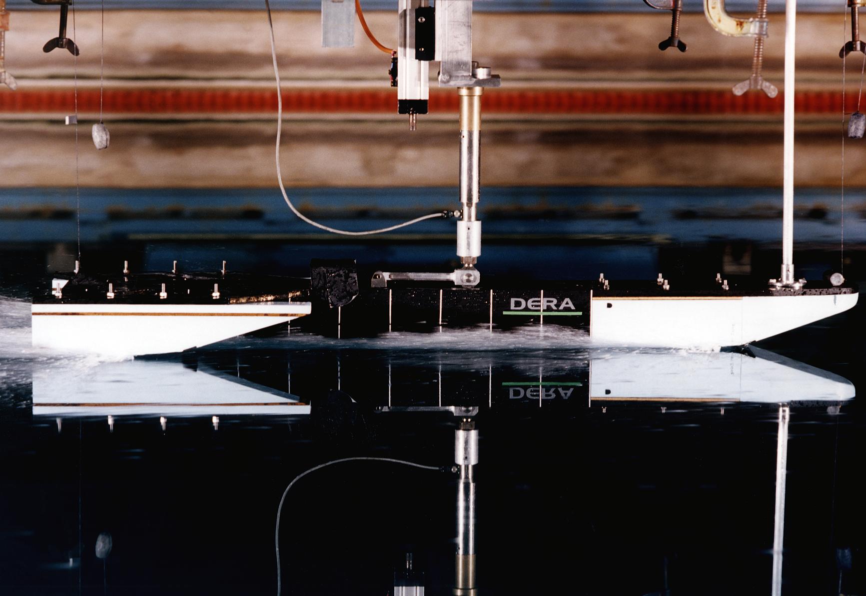
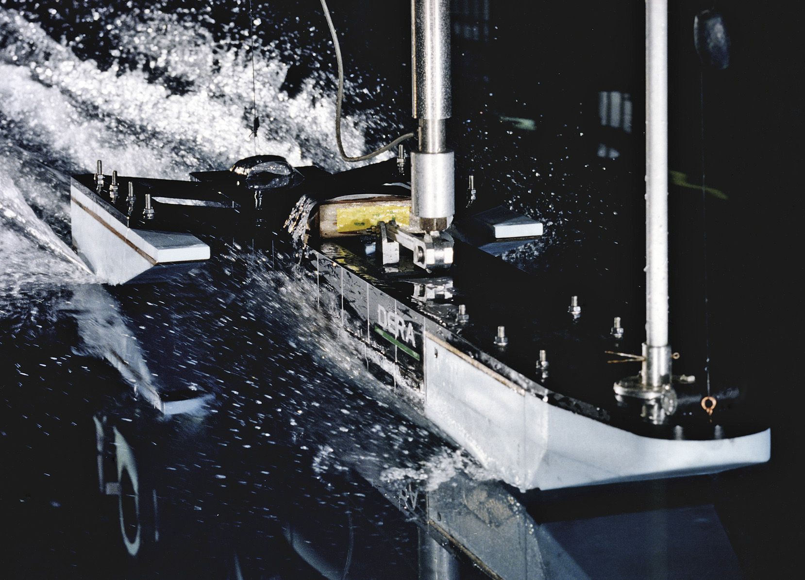
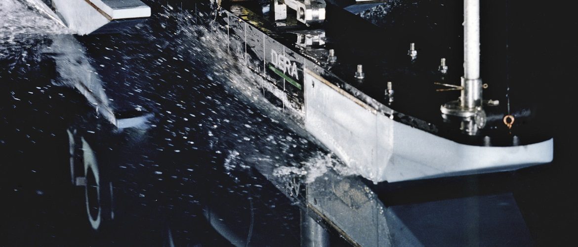
Over 120 test runs were conducted in a towing-tank with this 1/8th-scale model of an earlier Quicksilver concept. The hull configuration showed considerable promise in both windtunnel and water-tank testing. So much so that construction of the full-size craft was commenced. But a decision was eventually taken to alter direction and rework the design to create the potentially even better configuration we have today.
Our towing-tank tests took place at the DERA/BMT (later QinetiQ) Centre for Marine Technology at Haslar, near Portsmouth, and simulated the crucial displacement-to-planing phase, when the boat accelerates from a standstill to speeds of up to 70 mph (115 kph), whereafter it behaves as a hydroplane.
The white parts of the model were interchangeable to allow different hull shapes to be appraised. The model was mounted such that dynamic measurements could be made in the six degrees of freedom (6DoF) – pitch, roll and yaw, heave, surge and sway – and all of these movements were recorded for subsequent analysis.
Ken Norris directed the towing-tank test programme. Prior to the tests at Haslar, we undertook exploratory towing-tank trials at Southampton University with another model.
Free-running model tests
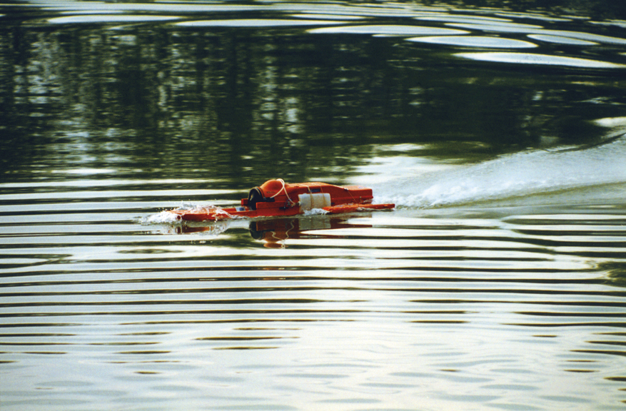
Several line-towed and radio-controlled models were built to assess the hydrodynamic performance of contrasting hull configurations. Tests in an unrestricted open-water environment enable higher speeds than are feasible in enclosed towing-tank facilities, where mechanical constraints tend to limit speeds.
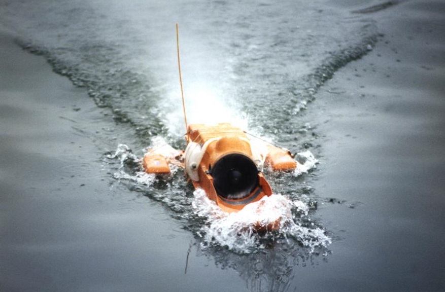
The hull configuration of the 1/8th-scale model seen here is the same as that of the model shown in towing-tank testing above, but this model had a ducted-fan propulsion unit. It is pictured accelerating at the start of a high-speed run on a private lake near Fordingbridge in Hampshire.
There were large numbers of test runs, and key data were recorded for analysis. Powered models had either ducted-fan or gas-turbine engines and interchangeable bow and sponson elements, so that different hull shapes and planing-surface angles could be evaluated. The work often required great patience, particularly when waiting for favourable weather and smooth water conditions.
Bruce White conducted the majority of our testing with free-running models, assisted by Nigel Christopher. The research was directed by Ken Norris initially, and later by Mike Green. The model shown here was built by Stuart Delf, assisted by Jim Fox.
Images © QWSR Ltd.